Chapter 1
Networking
Networking is the construction or process of connecting
multiple networks as they can communicate properly. Network is a collection of
physical devices like Computers, Routers, Switches, Hub, Bridges, Gateways, and
Firewall etc.
Network Segmentation:-
Breaking of large network into small
networks is called network segmentation.
Network Devices:-

Routers: - Routers
are used to connect networks together and route packets of data from one
network to another. Routers break up a broadcast domain. When the router’s interface receives
this broadcast it discard the broadcast without forwarding it on to other
networks.
Functions of Router: - There are following function of a router.
A). Path Selection
B). Packet Filtering
C). Packet Switching
D). Internetwork Communication
Router is a Layer 3 device and support Layer 3 addressing called
IP Address. It uses IP address to send packets. Router maintain a table called
Routing table that contains all best route to reach destination,
Routers use a routing table o make path selections and to forward
packets to destination network.
Switch:- By default, switches break up collision domains, Switches create separate collision domains, but a single broadcast
domain. Switch is a Layer 2 device by default. It forwards frames using MAC address. MAC address is a 48 bit permanent address;
this is also called physical address.
Firewall:- A firewall is a network security system, either hardware-
or software-based, that controls incoming and outgoing network traffic based on
a set of rules.
OSI
(Open System Interconnection) Model
OSI model was introduced in 1970 to define standard for networking systems. The OSI has seven different layers, which are divided into two groups.
1. Host Layers: - Define how the applications
within the end stations will communicate with each other and with users.
2. Media Layers:- define how data is
transmitted end-to-end.

Application
Layer :-
User communicate to the computer using Application layer, for example, file transfers, e-mail,
remote access, network management activities, client/server processes,
and information location.
Presentation Layer: - Present data of
application layer. Data encryption and decryption is performed by
this layer.
Session Layer: - Responsible for making,
managing, and then terminate sessions between Presentation layer
entities. It keeps the data different of different application.
Transport Layer :- Provide end to end
data transfer service. It breaks the data into small segments. It use two
protocol TCP and UDP for data transfer. Transport layer also perform Windowing,
Flow control and virtual circuit.
Network Layer: - Responsible for
transferring data through data which are not locally attached. Segments are divided into packets by
Network layer. There are two types of packets on this layer:
1. Data packets
2. Route Update packets.
Data
Link Layer: -
Data Link layer ensures that messages are delivered to the proper device. It
formats the data packets into frames and attaches header containing source and destination
device MAC address.
Physical Layer: - Send and receive
bits and communicate to actual media. Bits contain value either 1 or 0.


Transmission Control Protocol


Chapter 2 Network Protocols
The DOD model is a Brief version of the OSI model, it has four
layers.
1.
Application
layer
2.
Host
to Host Layer
3.
Internet
Layer
4.
Network
Access layer
DOD and OSI Layers

TCP/IP Model Protocols

Application Layer Protocols
Telnet:- It is a protocol that allows a user to
access Telnet server or machine remotely through command line.
TFTP:- TFTP (Trivial File Transfer Protocol) is used
to transfer file over the network. It does not provide the directory browsing
feature. So to use this protocol we must know the exact file name and location
of file.
FTP:- FTP(File Transfer Protocol) is actual file transfer protocols. We can
transfer data or file using the FTP protocol. FTP is not just a protocol, It is
a program also that provide directory browsing feature and let users select
data what they need to transfer.
SMTP:- SMTP(Simple Mail Transfer
Protocol) is used to send E-mail
messages. It is responsible for successful message delivery. It continuously check
queue for messages, as message comes in queue it process that message to
deliver.
LPD:- (Line Printer Daemon) is designed for printer sharing. It
allows to send print command over the network.
X Window:- X Window defines
a protocol for writing client/server applications
based on a graphical user interface (GUI). The idea is to allow a
program, called a client,
to run on one computer and have it display things through a window
server on another computer
SNMP:- (Simple Network Management Protocol) is used to collect information about network. It is also called
watchdog over the network. When any problem occur in network SNMP send alert to
the management machine.
NFS:- NFS(Network File System) is used for file sharing. It allows to different file systems to
share data.
Transmission Control Protocol
TCP:- TCP(Transmission
Control Protocol) take data payload from upper layers and break them into
segments.TCP is a connection oriented protocol , it means tit create a virtual circuit
before transfer data segments. It is also called hand shaking. During this initial handshake, the two
TCP layers also agree on the amount of information that’s going to be sent before
the recipient’s TCP sends back an acknowledgement. With everything agreed upon
in advance, the path is paved for reliable communication to take place.

Destination port :- The port number of the application
requested on the destination host.
Sequence number :- Puts the data back in the correct
order or retransmits missing or damaged
data, a process called sequencing.
Acknowledgement number:- Defines which TCP octet is expected
next.
Header length:- The number of 32-bit words in the TCP header. This indicates where
the data
begins. The TCP header (even one including options) is an integral
number of 32 bits in length.
Reserved:- Always set to zero.
Code bits :- Control functions used to set up and
terminate a session.
Window :- The window size the sender is willing
to accept, in octets.
Checksum :- The cyclic redundancy check (CRC),
because TCP doesn’t trust the lower layers
and checks everything. The CRC checks the header and data fields.
Urgent :- A valid field only if the Urgent
pointer in the code bits is set. If so, this value indicates
the offset from the current sequence number, in octets, where the
first segment of non-urgent
data begins.
Options:- May be 0 or a multiple of 32 bits, if
any. What this means is that no options have to be
present (option size of 0). However, if any options are used that
do not cause the option field to total
a multiple of 32 bits, padding of 0s must be used to make sure the
data begins on a 32-bit boundary.
Data :- Handed down to the TCP protocol at the Transport layer, which
includes the upper layer
headers.


User Datagram Protocol (UDP):- UDP is a connectionless transport layer protocol. The term connectionless means it does not create virtual circuit before start transfer data or it does not send SYN and Ack packets. UDP does not sequence the segments and does not care in which order the segments arrive at the destination. Because of this, it’s referred to as an unreliable protocol.UDP is very fast than TCP but not reliable. So where we need speed to transfer data we use UDP Ex. VOIP, for reliable communication we use TCP.


Port Numbers:- All protocols have a predefined port number on which they receive data or packets. To send data there must be both port number for source and destination, Source port assign randomly or dynamically but destination port number always be well known. Ports from 0 to 1023 are well known ports.

Internet Layer Protocol
- IP
- ARP
- ICMP
- Proxy ARP
IP :- IP receives segments from the Host-to-Host layer and fragments them into datagram’s if necessary. IP then reassembles datagram’s back into segments on the receiving side. Each datagram is assigned the IP address of the sender and of the recipient. Each router that receives a datagram makes routing decisions based on the packet’s destination IP address.

TTL:- The time to live is set into a packet when it is originally generated. If it doesn’t get
to where it wants to go before the TTL expires, This stops IP packets from looking for a destination .
Protocol:- Port of upper-layer protocol. Also supports Network layer protocols.
Header checksum: - Cyclic redundancy check (CRC) on header only.
Source IP Address: - 32-bit IP address of Source Device.
Destination IP address: - 32-bit IP address of the destination device.
IP options:- Used for network testing, debugging, security.
Data:- After the IP option field will be the upper-layer data.
ARP:- Address Resolution Protocol is used to resolve MAC address from IP address. If IP doesn’t find the destination host’s hardware address in the ARP cache, it uses ARP to find MAC.
ICMP:- Internet control messaging protocol is a management and messaging protocol for IP.
Proxy ARP:- Proxy ARP can actually help machines on a subnet reach remote subnets without configuring routing or even a default gateway. Proxy Using ARP will definitely increase the amount of traffic on your network segment, and hosts will have a larger ARP table than usual in order to handle all the IP-to-MAC address mappings
Connecting to Router :-We can connect Cisco router using Telnet, SSH, Console Cable
and ASDM. ASDM provide GUI console, But command line interface is the best way
to configure a Cisco router.
Logging to Router :-After router boot process complete Press Enter. Router will prompt router>. This is User
Exec Mode.
This mode is used to view the settings of router.
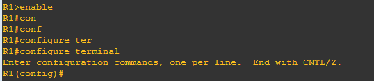
To change the router configuration you have to switch to Privilege Exec and Global Configuration mode.
To enter in Privilege Exec Mode type:- enable and
press enter
Ex. Router > enable
Router #
To exit from privilege mode :-
Router # logout
Or
Router # disable
Global Configuration Mode :- Change we make in this mode
will affect the entire router.
To enter in global configuration mode:-
If you make any change here, it will save in running config
file or RAM. To save changes in startup config or NVRAM enter the following
command
Copy runnig-config startup-config
How to configure cisco router
interfaces:- To configure interface use interface command in global configuration mode
Router(config)# interface ?
Ex:-

Choose interface which you wants to configure, I am going to
configure FastEthernet.
R1(config)#interface fastEthernet 0/0
R1(config-if)#
Notice that the prompt changed to Router(config-if)#? This tells you that you’re
in interface
configuration mode.
And wouldn’t it be nice if the prompt also gave you an indication
of what
interface you were configuring?
Available
commands in mode :-You can use ?
to check available commands in any mode

Set Clock in router:-
R1#clock set
R1#clock set ?
hh:mm:ss Current Time
R1#clock set 11:46:50 ?
<1-31> Day of the month
MONTH Month of the year
R1#clock set 11:46:50 29 september ?
<1993-2035> Year
R1#clock set 11:46:50 29 september 2015?
<1993-2035>
R1#clock set 11:46:50 29 september 2015
R1#
*Sep 29 11:46:50.000: %SYS-6-CLOCKUPDATE: System
clock has been updated from 01:22:08 UTC Fri Mar 1 2002 to 11:46:50 UTC Tue Sep
29 2015, configured from console by console


Routing :- Routing :- Routing is used for taking a packet from one device and sending it through the network to another device on a different network. The logical network address of the destination host is used to get packets to a network through a routed network, then the hardware address of the host is used to deliver the packet from a router to the correct destination host.
· Destination address

Router Command History:-
Command
|
Result
|
Ctrl+P or Up arrow
|
Shows last command
|
Ctrl+N or Down arrow
|
Shows previous commands
entered
|
show history
|
Shows last commands
|
show terminal
|
Shows terminal
configurations and history buffer size
|
terminal
history size
|
Changes buffer size (max
256)
|
Ex. Show history:-

Ex. Show terminal command

Change history buffer size :-
Setting Passwords: - There are five passwords used to
secure your Cisco routers: console, auxiliary, telnet (VTY), enable password,
and enable secret.
Enable Passwords
You set the enable passwords from global configuration mode like
this:
Router(config)#enable ?
last-resort :- Define enable action if no
TACACS servers
respond
Password:- Assign the privileged level password
Secret:- Assign the privileged level secret
use-tacacs:- Use TACACS to check enable
passwords
The following points describe the enable password parameters:
Last-resort:- Allows you to still enter the router if you set up authentication
through a TACACS
server and it’s not available. But it isn’t used if the TACACS
server is working.
Password :- Sets the enable password on older,
pre-10.3 systems, and isn’t ever used if an enable
secret is set.
Secret :- encrypted password that overrides the enable
password if it’s set.
Use-tacacs This tells the router to authenticate
through a TACACS server. It’s convenient if you
have anywhere from a dozen to multitudes of routers, because,
well, would you like to face the fun
task of changing the password on all those routers? If you’re
sane, no, you wouldn’t. So instead,
just go through the TACACS server, and you only have to change the
password:
Router(config)#enable secret cisco
User mode password:- User-mode passwords are assigned by
using the line command:
Router(config)#line ?
<0-70> First Line number
aux Auxiliary line
console Primary terminal line
tty Terminal controller
vty Virtual terminal
Auxiliary Password
To configure the auxiliary password, go into global configuration
mode and type line
aux ?.
Router#config t
Enter configuration commands, one per line. End with
CNTL/Z.
Router(config)#line aux ?
<0-0> First Line number
Router(config)#line aux 0
Router(config-line)#login
Router(config-line)#password cisco
It’s important to remember
the login command, or the auxiliary port won’t
prompt for
Authentication.
Console Password
To set the console password, use the line console 0 command.
Router(config)#line console 0
Router(config-line)#
password cisco1
Router(config-line)#
login
Additional Commands
Router(config)#line con 0
Router(config-line)#exec-timeout ?
<0-35791>
Timeout in minutes
Router(config-line)#exec-timeout 0 ?
<0-2147483>
Timeout in seconds
<cr>
Router(config-line)#exec-timeout 0 0
Router(config-line)#logging synchronous
The exec-timeout
0 0 command sets the
timeout for the console EXEC session to zero, which basically means to never
time out. The default timeout is 10 minutes
Logging synchronous stops annoying console messages from popping up and disrupting the
input you’re
trying to type. The messages still pop up, but you are returned to
your router prompt without your input interrupted.
Telnet Password
To set the user-mode password for Telnet access into the router
use the following command
Router(config-line)#line vty 0 ?
<1-4> Last
Line Number
<cr>
Router(config-line)#line vty 0 4
Router(config-line)#
password cisco2
Router(config-line)#
login
Encrypting Your Passwords
By default only secret password is
encrypted, all other passwords are in plain text. To encrypt all passwords we
have use following command
Router(config)#service password-encryption
Routing :- Routing :- Routing is used for taking a packet from one device and sending it through the network to another device on a different network. The logical network address of the destination host is used to get packets to a network through a routed network, then the hardware address of the host is used to deliver the packet from a router to the correct destination host.
To be able to route packets, a router must know, at a minimum, the following:
· Neighbour routers from which it can learn about remote networks
· Possible routes to all remote networks
· The best route to each remote network
· How to maintain and verify routing information
The router builds a routing table that describes how to find the remote networks. If a network
is directly connected, then the router already knows how to get to it. If a network isn’t
Connected, the router must learn how to get to the remote network in two ways: by using static
Routing, meaning that someone must hand-type all network locations into the routing table, or
Through something called dynamic routing.
There are three types of routing
1. Static
2. Default
3. Dynamic
Static Routing
Static
routing occurs when you manually add routes in each router’s routing table. Static routing has the following benefits:
No CPU
overhead
No bandwidth
usage between routers
Only
Administrator can choose allowed network
Static routing has the following
disadvantages:
Administrator must really understand the internetwork and how each
router is connected
in order to
configure routes correctly.
Administrator
has to add a route to it on all Routers manually.
Not feasible
in large networks because maintaining it would be a full-time job in itself
Command Syntax
ip route [destination_network] [mask] [next-hop_address or
exitinterface]
[administrative_distance] [permanent]
IP route:- The command used to create the static route.
Destination network: - The network you’re placing in the
routing table.
Mask: - The subnet mask being used on the
network.
Next-hop address:-The address of the next-hop router
that will receive the packet and forward
it to the remote network.
Exit interface: - You can use it in place of the
next-hop address if you want, but it’s got
to be on a point-to-point link, such as a WAN. This command won’t
work on a LAN such
as Ethernet.
Administrative distance :- By default, static routes have an administrative distance of 1 (or
even 0 if you use an exit interface instead of a next-hop
address). You can change the default
value by adding an administrative weight at the end of the command.
Permanent :-If the interface is shut down, or the router can’t communicate to
the next-hop
router, the route will automatically be discarded from the routing
table. Choosing the permanent
option keeps
the entry in the routing table no matter what happens.
Example:-
Router(config)#ip route 172.16.3.0 255.255.255.0
192.168.2.4
The ip
route command tells us
simply that it is a static route.
172.16.3.0 is the remote network we want to send packets to.
255.255.255.0 is the mask of the remote network.
192.168.2.4
is the next hop, or router, we will send packets to.

In this topology we are going to configure Default Routing on R1
To configure default routing on R1 command is :-

How to enable default routing on cisco router
Default Routing
We use default routing to send packets with a remote destination network not in the routing
table to the next-hop router. You can only use default routing on stub networks those with
only one exit path out of the network.
To configure a default route, you use wildcards in the network address and mask locations
of a static route.

R1(config)#ip route 0.0.0.0 0.0.0.0 10.1.1.2
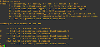
To check routing table command is
R1#show ip route

Dynamic Routing
Dynamic routing is when protocols are used to find networks and
update routing tables on routers.
A routing protocol defines
the set of rules used by a router when it communicates routing information
between neighbor routers.
Routing Protocols
RIP
EIGRP
OSPF
IS-IS
BGP
Routing Protocol Basics
There are some important things you should know about routing
protocols before getting
deeper into RIP. Specifically, you need to understand
administrative distances, the three different
kinds of routing protocols, and routing loops. We will look at
each of these in more detail
in the following sections.
Administrative Distances
The administrative
distance (AD) is used
to rate the trustworthiness of routing information
received on a router from a neighbour router. An administrative
distance is an integer from 0 to
255, where 0 is the most trusted and 255 means no traffic will be
passed via this route.
If a router receives two updates listing the same remote network,
the first thing the router
checks is the AD. If one of the advertised routes has a lower AD
than the other, then the route
with the lowest AD will be placed in the routing table.
The advertised route with
the lowest metric will be placed in the routing table. But if
both advertised routes have the same AD as well as the same
metrics, then the routing protocol
will load-balance to the remote network.
Default Administrative
Distances
Connected interface 0
Static route 1
EIGRP 90
IGRP 100
OSPF 10
RIP 120
External EIGRP 170
Unknown 255 (Invalid Route)

Routing Loops
A routing loop is a situation where a packet keeps getting routed between two or more routers because of problems in the routing table. In case of distance vector protocols, the fact that these protocols route by rumor and have a slow convergence time can cause routing loops.
Split Horizon
solution to the routing loop problem is called split horizon. This reduces incorrect routing
information and routing overhead in a distance-vector network by enforcing the rule that
routing information cannot be sent back in the direction from which it was received.
In other words, the routing protocol differentiates which interface a network route was
learned on, and once this is determined, it won’t advertise the route back out that same interface.
Route Poisoning
Another way to avoid problems caused by inconsistent updates and stop network loops is route
poisoning. For example, when Network 5 goes down, Router E initiates route poisoning by
advertising Network 5 as 16, or unreachable (sometimes referred to as infinite).
This poisoning of the route to Network 5 keeps Router C from being susceptible to incorrect
updates about the route to Network 5. When Router C receives a route poisoning from Router E,
it sends an update, called a poison reverse, back to Router E. This ensures all routes on the segment
have received the poisoned route information.
Routing Information Protocol .
Route poisoning and split horizon create a much more resilient and dependable distancevector
network than we’d have without them, and they serve us well in preventing network
loops.

Hold-down
A hold down prevents regular update messages from reinstating a route that is going up and
down (called flapping). Hold down prevent routes from changing too rapidly by allowing time for either the downed route to come back up or the network to stabilize somewhat before changing to
the next best route. These also tell routers to restrict, for a specific time period, changes that
might affect recently removed routes.
When a router receives an update from a neighbor indicating that a previously accessible network
isn’t working and is inaccessible, the hold down timer will start. If a new update arrives
from a neighbor with a better metric than the original network entry, the hold down is removed
and data is passed. But if an update is received from a neighbor router before the hold down
timer expires and it has an equal or lower metric than the previous route, the update is ignored
and the hold down timer keeps ticking. This allows more time for the network to stabilize before
trying to converge.
Hold downs use triggered updates that reset the hold down timer to alert the neighbor routers
of a change in the network. Unlike update messages from neighbor routers, triggered updates
create a new routing update that is sent immediately to neighbor routers because a change was
detected in the internetwork.
There are three instances when triggered updates will reset the hold down timer:
The hold down timer expires.
Another update is received with a better metric.
A flush time, which is the time a route would be held before being removed, removes the
route from the routing table when the timer expires.
No comments:
Post a Comment